Mod: Rear Air Springs

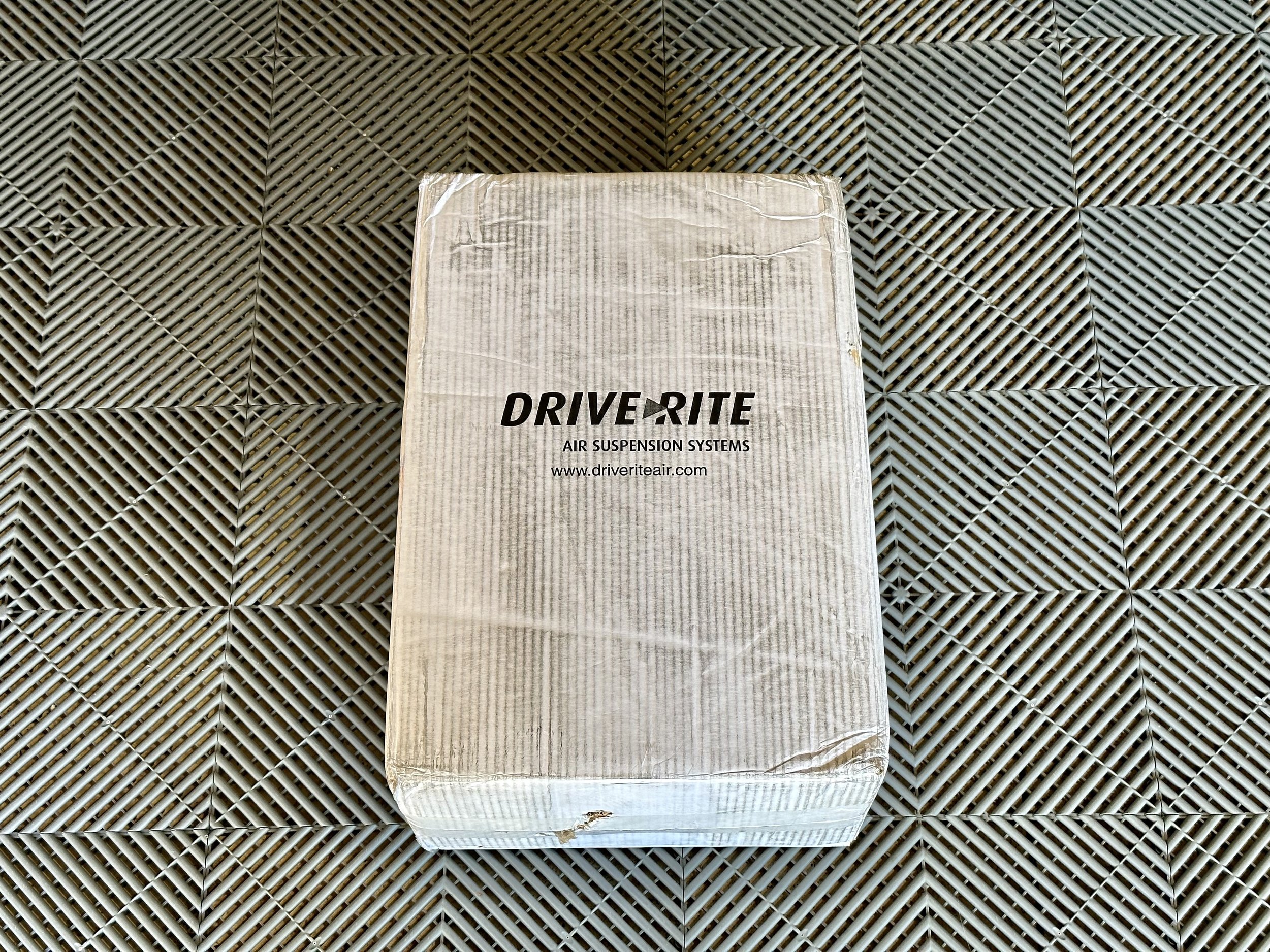
These are the contents of the two kits with everything you need — comes in a single box.

Air spring installed. Attached in-between a top and bottom bracket in the space where the factory bump stop used to live. The air spring appears taller not because it’s overfilled with air, but because the levelers are extended and the rubber is stretched.

Dual air gauge controls installed in the cab (low and to the left of the steering wheel). Both air springs can be controlled independently to level a side-to-side load. It’s not uncommon to require a 3 bar pressure difference between the two sides to keep the rig level.

Compressor pump installed in exterior compartment behind driver’s door. Also pictured is the included/required black relay that provides power to the pump on demand.

Both air springs installed where the factory bump stops used to operate.

Video overview of air spring inflation/deflation and driving examples.


Everything fits in this shipping box.

Close-up of dual air gauges and controls before installation.

Close-up of compressor pump before installation.

These are the things that are removed to make room for the air spring kit. Pictured are the top rubber bump stops, the bottom metal bump stop (with torx bolts) and a “latch” that needs to be cut or sawed off where the driver’s side bottom air spring bracket will be installed.

Installation begins. Rear rubber bump stop has been removed prior to this photo. In its place is the first of three pieces that make up the top bracket for the air spring. The bracket attaches to the same area as the factory rubber bump stop.

Top bracket installed (made up of three parts that are connected together by two bolts). No holes are made in chassis.

Air spring with top air valve and bottom bracket attached.

This is the passenger’s side. The bottom metal bump stop (circled) needs to be removed from both sides. It’s an easy removal — just two torx bolts hold it in place. Its removal makes room for the bottom air spring bracket.

Also passenger’s side. The protruding attach point (circled) that remains after removing the lower metal bump stop is part of the extended leaf spring spacer. It is in the way of where the air spring’s lower bracket will sit, so the spacer needs to rotate 180 degrees such that the protruding section points toward the wheel instead of toward the differential.

LONG ARROW: This is the driver’s side extended leaf spring spacer already turned 180 degrees to allow space for the bottom air spring bracket.
SHORT ARROW: This “latch” needs to be cut off or sawed off the driver’s side to make room for the bottom air spring bracket. This latch only exists on the driver’s side for an auto-leveling headlight sensor which our rigs don’t have. An angle grinder, hacksaw or Dremmel tool can all do the job. It’s daunting at first, but it’s not structural and it doesn’t affect anything negatively in the future, including a reversal of this air spring mod.

Another angle of the “latch” that needs to be removed (only found on the driver’s side).

Close-up of the “latch” that needs to be removed (only found on the driver’s side). The red line indicates where it needs to be cut.

This is a test fit of the driver’s side air spring bottom bracket BEFORE the latch is removed. Note how the bottom bracket is raised up and obstructed from sitting lower because the latch is in the way. This is why the latch needs to be removed.

Latch is removed! It’s important to then clean the area and protect it with a Rust-Oleum-type paint to prevent rust or corrosion in the future.

Close-up of the “latch” that needs to be cut off or sawed off. There is only one of these (on the driver’s side near the axle). It’s an unused attach point for a self-leveling headlight sensor which isn’t an option on our rigs.

Driver side air spring installed. Attached in-between a top and bottom bracket in the space where the factory bump used to live. The air spring appears taller not because it’s overfilled with air, but because the levelers are extended and the rubber is stretched.

Under hood, engine compartment, right side. Arrow points to existing hole and grommet in firewall which serves as the access to route the air lines and wires into the cab.

Under hood, engine compartment, right side. Arrow points to existing hole and grommet in firewall which serves as the access to route the air lines and wires into the cab.

Hole/grommet sealed with automotive black rubber sealant.

Under hood, engine compartment, right side. Arrow points to existing ground connection where I added the ground wire from the dual gauge control unit.

Added black rubber sealant to the grommet where the compressor air line and wires pass-through.

I temporarily removed my HWH control panel in order to mount a light, dimmer switch and master compressor switch to the bottom of this panel.

From right to left, an LED light, grommet, dimmer switch and master compressor switch on the bottom of the HWH control panel. This dimmable light illuminates the dual air gauges below it (when mounted on the dash). The master switch cuts power to the air spring compressor pump.

Nighttime shot of the dimmable light illuminating the dual air gauge controls.