Mod: Electric Waste Valve


DETAILS: Electric Waste Valve System
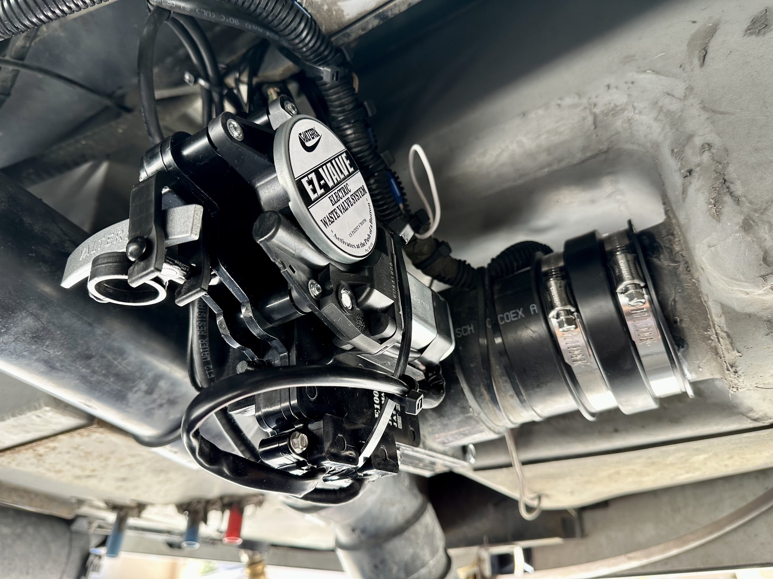
I’ll start by saying I should have done this a long time ago. Have you ever had a waste tank valve not close completely and surprise you the next time you dumped? I finally found a permanent solution to my problem! The Valterra Electric Waste Valve System is a high-tech solution with a high-torque motor. The included switch (with switch plate) has a light which won’t turn off unless the valve is 100% closed (verified by a built-in sensor). I now have a visual indicator and full confidence that my valve is, in fact, closed! The system has a built-in manual override handle so you can operate the valve without power (though it would require reaching under the coach in that “emergency” situation). Total install takes between 1 and 2 hours.
The Problem
In my 2018 J, the black tank valve is a cable valve (due to the reverse orientation of the valve and desired handle placement, there is a long cable in a sheath that connects the two instead of a solid push rod). Unfortunately, Winnebago did not install the valve and handle per Valterra’s minimum 24” radius specifications. As a result, the radius of the 180° bend in the cable is half the diameter that Valterra specifies and leverage on the valve control is lost in the process due to increased friction. What does this mean? Over time, it becomes difficult (if not impossible) to fully close the valve, no matter how firmly or how long you push on the cable valve handle. After being surprised at the dump station one too many times, I began reaching under the coach and pulling the small silver cylinder at the end of the cable and manually closing the valve the last 1/2” or so. I have never had a leak since! But it’s a dirty job at an awkward angle and I ultimately pulled a muscle in my shoulder in the process.
Before you Begin
It’s important to not only empty all of your tanks before you start, but also flush your black tank as clean as possible. Some dripping on the ground is inevitable when you loosen the flexible couplings and remove the valve(s), and you want that water to be as clean as possible. It wasn’t the dirty job I feared! And while I was working on the sewer plumbing, I decided to proactively replace the gray tank Bladex valve and both flexible couplers — it was the perfect opportunity to renew these aging components (all details below).
PLEASE NOTE: although this post may seem detailed, I don’t include a lot of things that are in the product’s instructions, so please be sure to read them before you start this project.
Installation of Electric Waste Valve
On my coach, the new electric valve replaced my black tank valve (which was a cable-driven valve from the factory). On some coaches, the gray tank is a cable valve. If you’re lucky, neither are cable-driven! If space allows, you can also replace a standard Bladex valve with an electric valve. On my rig, there wasn’t room, but since I needed to disconnect the sewer plumbing anyhow, it was the perfect time to replace the standard gray valve with a new one (mine was already 5 years old and not operating as smoothly as it once did).
To provide the needed flexibility and movement of the sewer connections, begin by loosening both black rubber couplers that connect the plumbing to both tanks. Next, unscrew the extension rod of the standard Bladex valve (on my rig, this was connected to the gray tank). The extension rod is threaded and unscrews from the valve which will require a couple sets of pliers to undo so the rod doesn’t just spin in the valve. IMPORTANT: there is no need to fully remove the extension handle — just leave it in place, disconnected (see photos).
The order in which you replace the valves and the couplers is up to you. In my case, I was replacing four things total: two valves and two couplers. I started with the standard gray valve which is very straightforward. Remove the four bolts/nuts, then remove the old valve and the old seals. Clean up any areas where the new seals and valves will make contact. Insert the new seals on the flanges (not the valve). Carefully insert new valve without disturbing or pinching the seals. Insert the 4 new bolts and evenly tighten all 4 nuts.
The installation is identical for the electric valve (refer to the included printed instructions). Once the bolts are evenly tight, use large, heavy duty zip ties to help support the weight of the valve/motor assembly. On my rig, there are perfectly positioned anchor points on the vehicle’s chassis directly above the valve.
Electrical Wiring
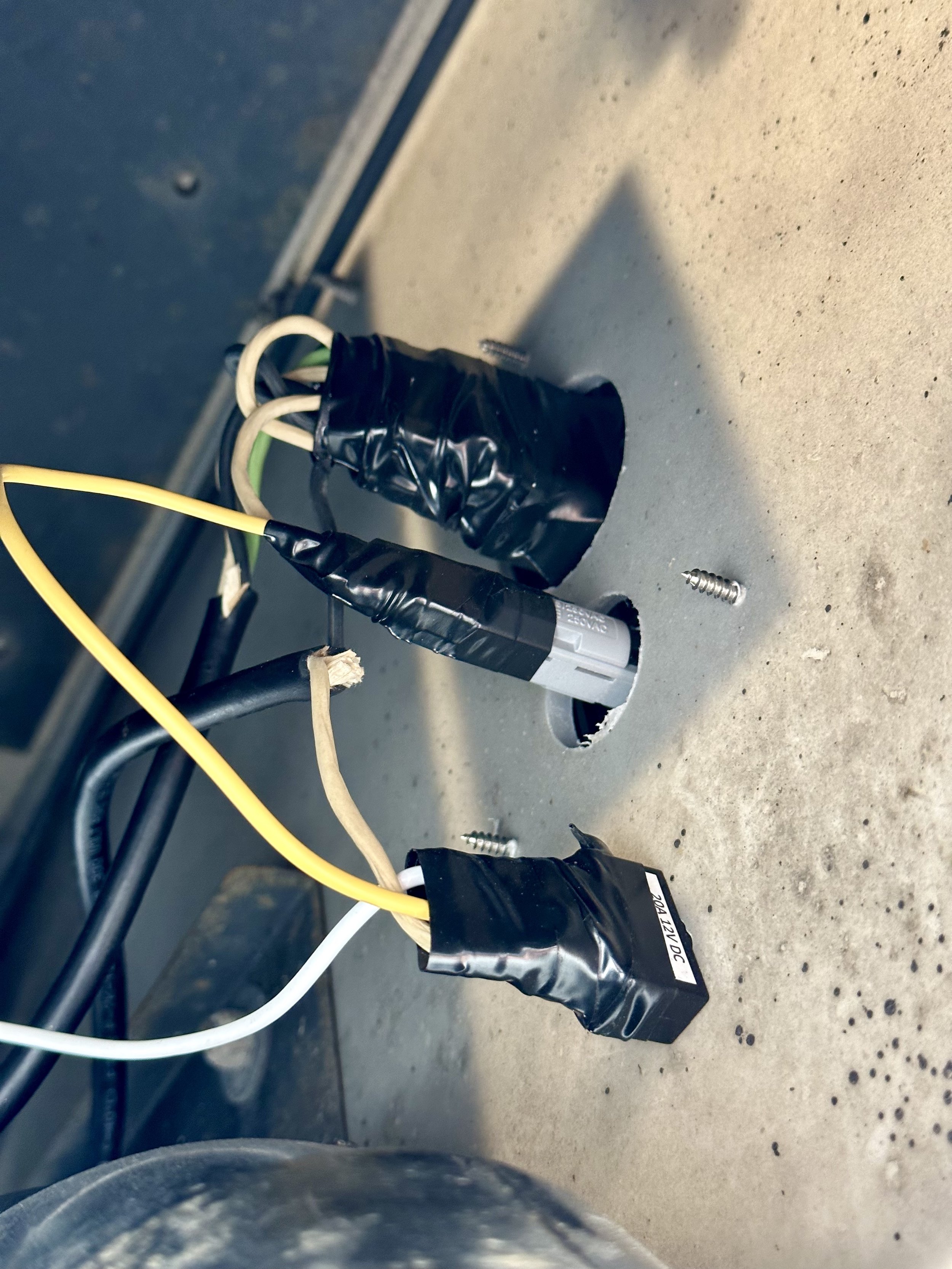
The easiest and most accessible power source is the power running to the tank heaters — located about 12 inches from the electric valve. I used quick splice connectors to “steal” power (yellow) and ground (white) from the leads going to the nearby tank heater pads. PLEASE NOTE: this is switched power and it’s only hot when the tank heater switch is turned on inside the coach. I used this power source intentionally so I have a built-in safety guard. As a result, the electric waste valve is always off and “cold” unless I provide it power with the tank heater switch. Leaving the tank heaters on while dumping has no ill effect on your batteries. In fact, if it’s not cold enough outside, the tank heaters won’t actually heat at all since they are thermostatically operated. When not dumping, and when not cold outside, I leave the tank heaters off. To avoid an accidental dump when the tank heaters are actually in use during cold weather operations, I installed a secondary lighted toggle switch adjacent to the dump switch to cut power (see details below).
Main Switch Installation
To install the main dump switch, drill two large holes via the included printed template and guide. The system comes with two switch plates, black and gray. Since my install is for the black tank, I used the black switch plate (pictured). I used electrical tape to help weatherproof the exposed electrical connections since the back of the switch is technically exposed to the elements on the outside of the service bay (see photos). Conveniently, no further wiring is necessary once you run the power and ground wires in the step above — the switch and fuse come prewired as pictured and it’s a simple plug and play multi-pin connector from there!
Installation of Secondary Lighted Toggle Power Switch
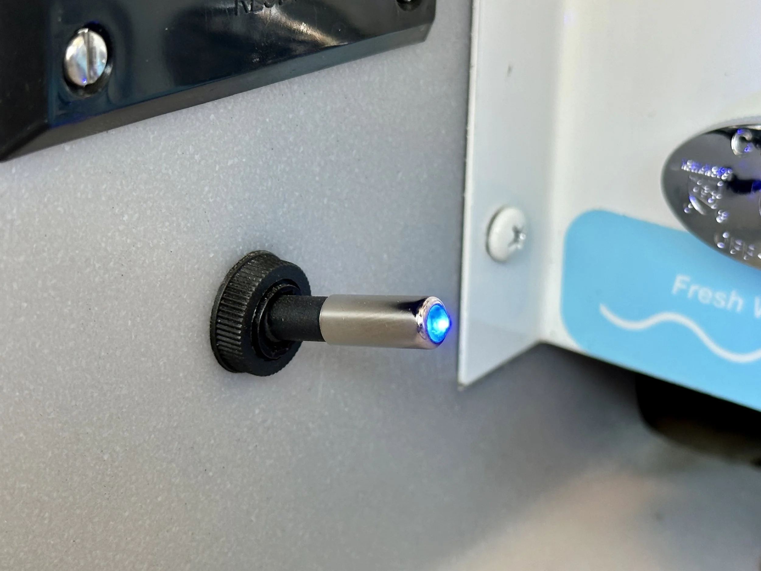
In addition to the “master” power of the tank heater switch, I added a 12v switch to cut power to the electric waste valve when not dumping to avoid any possibility of an accidental dump! It’s now a 3-action operation (first the tank heater switch, then the power switch, then the dump switch). Any 12vdc switch will work, but I choose a toggle switch with a bright blue LED light that is clearly visible even in the daytime (the light requires a ground connection which I quick spliced from the same tank heater ground source).
I wired the 12v toggle switch to the built-in fuse in the waste valve switch. So, the added toggle switch interrupts the power being provided to the main switch fuse. Once the toggle switch is turned on, power flows to the waste valve switch normally.
Manual Override
The design of the valve is simple, as is the manual override, since the high-torque motor is merely holding onto and moving a traditional pull handle. To operate the handle manually, remove the ring pin from the valve lift arm. Turn the valve handle 90° to clear the lift arm. Pull (and push) the valve handle to open and close the valve manually.
Installation of Flexible Couplers
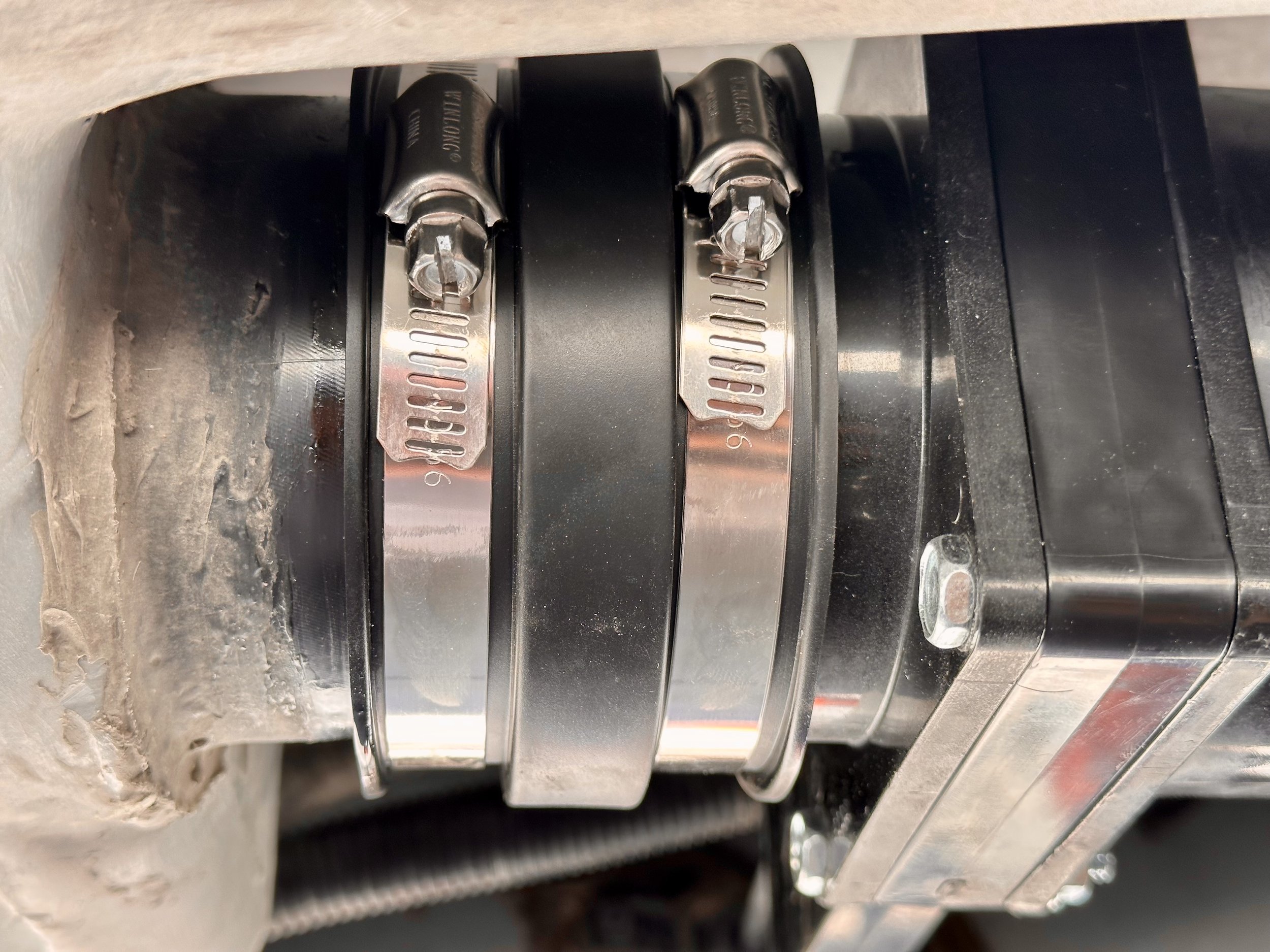
My couplers were just over 5 years old and cracking badly (see photos). I first noted the aging and cracking after 2-3 years, and it seemed it was only a matter of time that a leak could spring, so I decided to preemptively replace them while replacing the valves. These new flexible couplers are made of much higher quality rubber than OEM, and I expect they’ll last a long time.
On my rig, only one of the two hose clamp screws was accessible on each coupler, but that’s all you’ll need to begin to disconnect the sewer plumbing. Once one of the screws is loose and you can move the plumbing, you’ll gain access to the other screw to remove the coupler. I cleaned the areas where the new couplers would attach to assure the best seal. I also used silicone spray to lubricate the surface area to allow the new coupler to slide on more easily (silicon is safe to use on these materials). Wait to tighten the new couplers until the new valve(s) are in place.
Valterra 3” Electric Waste Valve: www.amazon.com/dp/B004RCXC1G
Valterra 3” Standard Bladex Valve: www.amazon.com/dp/B000BGK22E
Valterra 3” Flexible Coupler: www.amazon.com/dp/B00PHNCU30
12v Lighted Switch: www.bit.ly/3B2bPxr
Installation Instructions: www.bit.ly/45lgvg6